31+ autocad 3d isometric view to 2d
U xcos α ycos α120 zcos α-120 v xsin α ysin α120 zsin α-120 although for C youll have to convert to radians. Isometric drawings begin with one vertical line along which two points are defined.

Presentation On Autocad Engineering Infinity Facebook
To Choose a 2D Isometric Drawing Plane.

. Go to the control bar and click at the triangle place next to the symbol 3D mode. One contains the 2D views and the other a 3D model. If you want to draft isometric in 2D change first your crosshair in iso plane ie.
Each CAD and any associated text image or data is in no way sponsored by or affiliated with any company organization or real-world item product or good it may purport to portray. Click inside the drawing view border to select the drawing view. Type Perspective 1 to indicate that you want to view your design with perspective which means that parallel lines will appear to converge as they do in the physical world.
Move the cursor over the drawing view to move. Give isometric drafting a spin sometime. Choose View 3D Views Southwest Isometric to be sure you are not in an existing camera view.
Follow these steps to produce a 2D view from a 3D model. On the status bar click the drop-down arrow on the Isometric Drafting status bar button and select the desired isoplane Find. Go to the 2D drawing and give the PASTESPEC Paste Special command.
Please excuse me but I have to show off my latest CAD efforts. Relative to UCS If the object is tall then lower the vertical relative to UCS angle to see inside your object 353 modified to 25 for example. Simulate an isometric view of a 3D object by aligning objects along three major axes.
It will create a 2D drawing of whatever solids are in modelspace from whichever perspectives you have selected and you will generate and view them in your paperspace but you do not use a. Up to 9 cash back So there you have it. I dont think you will be able to use the isometric from ACAD to trace over.
When you enable the 3D mode the 3D display status at the display box of 3D setting will get ON. Launch the command DDVPOINT and see the angle. A 2D isometric drawing is a flat representation of a 3D isometric projection.
Choose View Named Views. 30x60 deg by going to OSNAP object snap button in your autocad window right click on it then click settings then pick snap and grid button click isometric snap under snap type click ok. Select from a dialog box choose a symbol and the view you need.
I started with the intent to show the forward former the longitudinal member and the aft sub-former and the wing dowel receptacles. Drag the grip to move the drawing view to the desired location. How do I get 3d view in 2d Autocad.
Give the HIDE command and select the geometry. Just load the library in AutoCAD then click and insert the iso block or. The drawing view border appears.
The ACAD isometric is really just a flat xy drawing. In the 3D model go to a viewing angle that shows the solid model in the isometric orientation you want. Choose a category of symbols from a pull-down menu that is fully integrated into AutoCAD or LT.
Use CTRL-C to copy the lines to the Windows clipboard. If you do some 3D work take a standard isometric point of view then modify it to see better the objects. Click the plus sign beside Model.
All that a dimetric view requires is a from the x-axis value of 45 135 225 or 315 AND an angle from the XY plane of anything greater than 0 and less than 90. Autocad 2012 introduced the VIEWBASE function which will automatically extract any or all eight standard perspectives four orthogonal and four isometric. Set DISPSILH to 1.
In revit you draw your piping where it actually goes. The world of isometrics in AutoCAD is pretty easy once you know whether youre talking 2D or 3D. To be able to convert your drawing into a 3D model we require that your drawing has at least a Front View a Top View and a Side View.
Then hide all but the pipes fittings and fixtures in. Pick a viewing angle in the 2 graphics Left graphic From X Axis Right graphic In XY Plane 5. Just so how do you draw isometric in AutoCAD 2018.
The Computer-Aided Design CAD files and all associated content posted to this website are created uploaded managed and owned by third-party users. Set the visualstyles to 2D Wireframe. α will rotate your view choose however you want to align stuff.
Originally I wanted a simple isometric view to show the wing mounting detail of this airplane. Isometric drawing in AutoCAD can be made by tilting viewing angle to 30 degrees for all of its sides in the 2D plane29 avr. An isometric drawing is a 3D representation of an object room building or design on a 2D surface.
How do I copy and paste an isometric view in Autocad. Isometric drawings begin with one vertical line along which two points are defined. In the 3D model go to a viewing angle that shows the solid model in the isometric orientation you want.
We would prefer if an Isometric View was included as well. Set the current UCS as World the current view as SE Isometric and the current visual style to 2D Wireframe. Type DDVPOINT at the command prompt.
How do I copy and paste an isometric view in AutoCAD. However if the angle is 352644 you get an isometric. Give the HIDE command and select the geometry.
Navigate to an AutoCAD file with a 2-D model that you want to convert to 3-D and double-click on it. Use CTRL-C to copy the lines to the Windows clipboard. AutoCAD will load the file for you to convert.
You can now draw lines in either 30deg or 60deg plane by pressing the F5 button on the keyboard. AutoCAD 3D Workalong 30-1. Save and name the drawing.
Set a viewing angle by typing the From X axis and XY Plane angle. The beauty of this Iso Piping Library is theres nothing to learn. Click the Workspace Switching button on the.
Creating 2D Drawings from a Solid Model Step 1. AutoCAD 3D Tutorial - 15 - 110 DDVPOINT 1. The more views your drawing has the more detailed and accurate we can make your 3D model.
Trimetric projections are just any x axis direction other than 0 45 or 90 and any angle from the XY plane except 0 or 90. Let say you have two AutoCAD drawings. 5312019 In order to enjoy 3D viewing experience you need to follow below the below-mentioned steps for the setup process.
October 31 2012 0600 PM. By using the ISODRAFT command several system variables and settings are automatically changed to values that facilitate isometric angles. Using the NEW command start a new drawing using template.
In the 3D model go to a viewing angle that shows the solid model in the isometric orientation you want. TurboCAD - 2D Isometric. When you are finished with 2D isometric drawing click Find on the status bar to return to orthographic drawing.
Choose View 3D Views Viewpoint Preset. Give the HIDE command and select the geometry. A grip appears at the center of the view.
You can also view the camera using the view option when creating the camera. Insert the symbol in your AutoCAD drawing and rotate as needed. If you choose α as a multiple of 30 youll get fairly nice numbers involving just a simple square root.
Isometric drawings are not actual 3D drawings they are made with 2D geometries but they appear like 3D. One is simply a method of viewing your 3D models and the other refers to the tools commands and even tricks used to produce a 2D representation of a 3D object.

40 X 40 Ft 3bhk Latest House Plan House Plans House Front Design House

Restaurante Vespertine Culver City Ca Eric Owen Moss Architects Foto Tom Bonner Eric Owen Moss Architecture Parametric Architecture

Presentation On Autocad Engineering Infinity Facebook

Table With Chairs 3d Warehouse Round Dining Room Furniture Table

Pin On Modern Dollhouse

Infographic The Stages Of Discovery To Mine Production Life Cycles Infographic Engineering Poster

Pin On Paper Cuting
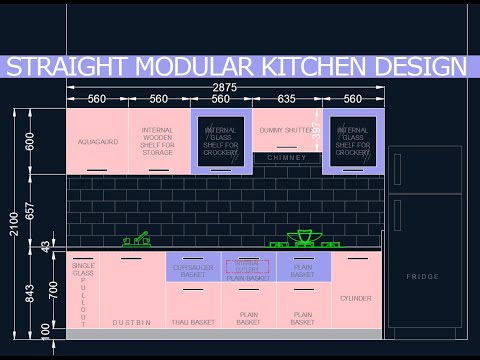
Kitchen Design Cad Free Detailed Login Instructions Loginnote

Toto Commercial High Efficiency Urinal Rectangle Urinal Conference Room Design Plumbing Installation

Presentation On Autocad Engineering Infinity Facebook
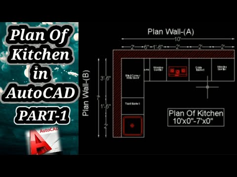
Kitchen Design Cad Free Detailed Login Instructions Loginnote
Manhole Chamber Section Autocad Drawing Free Download Autocad Autocad Drawing Brick Detail

42 X 62 House Floor With Master Plan Autocad File Ground Floor Plan House Flooring Master Plan

Manhole Chamber Section Autocad Drawing Free Download Autocad Autocad Drawing Brick Detail

Presentation On Autocad Engineering Infinity Facebook

The Remix 2016 Net Indonesia On Behance Stage Lighting Design Concert Stage Design Stage Design
Kitchen Design Cad Free Detailed Login Instructions Loginnote

Presentation On Autocad Engineering Infinity Facebook

The Remix 2016 Net Indonesia On Behance Stage Lighting Design Concert Stage Design Stage Design